
TFA Thin-Film Analyzer: Thermoelectric and Thermal Transport Characterization System for Nano- to Micrometer-Scale Thin Films
The physical properties of thin-film materials differ fundamentally from those of bulk materials. Due to their extremely small dimensions and high aspect ratios, surface-related effects play a much more dominant role in both thermal transport and electrical behavior. At nano- to micrometer scales, the following effects significantly influence thin-film properties:
- Enhanced surface scattering effects (a)
- Pronounced boundary scattering (b)
- Quantum confinement effects in ultra-thin layers (c)
The LINSEIS Thin-Film Analyzer (TFA) is specifically designed for high-sensitivity investigation of such thin-film characteristics. It provides a convenient, fast, and highly accurate measurement approach. Based on a patented measurement concept (patent pending), the system enables simultaneous determination of multiple thermal and electrical properties in a single measurement run.
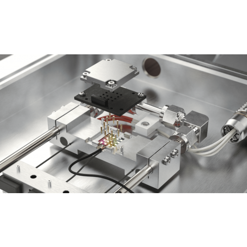
TFA System Configuration and Measurement Architecture
The basic system consists of a pre-structured measurement chip for rapid sample placement and a measurement chamber providing environmental control. Depending on application requirements, lock-in amplifiers and high-field electromagnet modules can be integrated. Most measurements are performed under UHV conditions, while LN2 cooling and heaters allow precise temperature control from -170°C to 280°C.
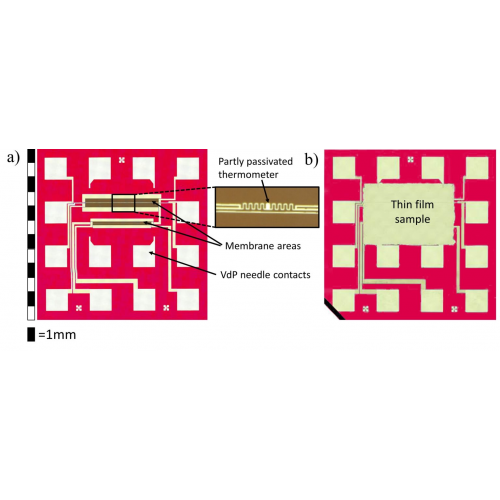
Pre-Structured Measurement Chip
Each chip integrates multiple measurement functionalities, including:
- 3ω heater/thermometer line for thermal conductivity measurement
- Four-point Van der Pauw structure for electrical characterization
- Integrated thermocouples for Seebeck coefficient measurement
The chip is compatible with thin films deposited by PVD (evaporation, sputtering, MBE), CVD (including ALD), spin coating, drop casting, and inkjet printing.
Once deposition is completed, thermal conductivity, electrical conductivity, and thermoelectric parameters can be fully characterized on the same platform.
.png)
Multiple Thin-Film Properties Obtained in a Single Measurement
All measurements are performed along the same in-plane direction, ensuring excellent data comparability.
-
1. Van der Pauw Measurement (σ, AH)
Four-point electrodes A/B/C/D are used with alternating current–voltage measurements to determine resistivity and electrical conductivity σ. Under an applied magnetic field, the Hall coefficient AH can also be determined. -
2. Seebeck Coefficient Measurement (S)
Local heaters and temperature sensors integrated on the chip enable measurement of the thermoelectric voltage Vth under defined temperature gradients. The Seebeck coefficient is calculated as S = –Vth / ΔT. -
3. Thin-Film Thermal Conductivity Measurement (3ω Method)
A suspended heater line is used simultaneously for heating and temperature sensing. In-plane thermal conductivity λ is derived from resistance changes and known geometrical parameters. Depending on the sample, specific heat and emissivity can also be evaluated.
*Optimal measurement quality is achieved when (film thickness × thermal conductivity) ≥ 2×10⁻⁷ W/K. -
4. Modular Expansion Capability
The basic system can be upgraded to include:- Thermoelectric module: measurement of σ, ρ, and S
- Magnetic module: measurement of Hall constant, carrier concentration, and mobility
.png)
TFA Package Options
Base System (Including Transient Package)
Includes measurement chamber, vacuum pump, heated sample stage, dedicated lock-in amplifier for 3ω measurements, PC, and LINSEIS software. Capable of measuring:
- Thermal conductivity λ
- Specific heat cp
- Emissivity ε (material dependent)
Thermoelectric Package
Includes DC electrical measurements and thermoelectric analysis software, enabling measurement of:
- Electrical resistivity ρ / electrical conductivity σ
- Seebeck coefficient S
Magnetic Package (Electromagnet / Permanent Magnet)
Optional 1 T electromagnet or ±0.5 T permanent magnet for measurement of:
- AH – Hall coefficient
- μ – Carrier mobility (model dependent)
- n – Charge carrier concentration (model dependent)
Low-Temperature Cooling Options
- LN2 cooling down to 100 K
- TFA/KREG controlled cooling module
- TFA/KRYO 25 L Dewar vessel
.png)
Technical Specifications
- Temperature range: Room temperature to 280°C; optional low-temperature operation down to –170°C
- Film thickness: 5 nm to 25 µm
- Measurement approach: Pre-structured measurement chips (24 pcs per box)
- Compatible deposition techniques: PVD, ALD, CVD, spin coating, inkjet printing, etc.
- Vacuum level: Down to 10–5 mbar
- Thermal conductivity range: 0.05 to 200 W/m·K
- Electrical conductivity range: 0.05 to 1×10⁶ S/cm
- Seebeck coefficient range: 5 to 2500 µV/K
- Repeatability:
- Thermal conductivity ±7%
- Electrical resistivity ±3%
- Seebeck coefficient ±5%
- Accuracy:
- Thermal conductivity ±10%
- Electrical resistivity ±6%
- Seebeck coefficient ±7%
- Interface: USB
* Specifications may vary depending on configuration and selected modules
Technical Videos
Mobile: +886-919-138-108
Email: Allen.kuo@fstintl.com.tw