
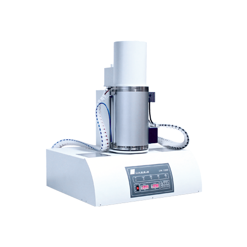
LFA 1000 Laser Flash: A Modular Flagship Platform for High-Temperature Thermal Conductivity Measurement
The LFA 1000 Laser Flash is a high-precision, modular measurement system designed for evaluating thermal conductivity (K-value) and related thermal properties. With multiple sample holder options, it supports various sample forms including solids, liquids, melts, and slags, meeting thermal property measurement needs from low to ultra-high temperatures.
An optional sample robot can automatically handle 3, 6, or 18 samples, significantly improving sample throughput. In addition, a wide selection of furnaces covers temperatures from -125°C up to 2800°C, addressing applications in electronic packaging, heat sink modules, support structures, reactor cooling, heat exchangers, and insulation materials.
Benefits of the Modular Design
- Upgradeable temperature range: Extend the upper temperature limit by replacing furnaces and measurement modules.
- Upgradeable infrared detector: Select InSb or MCT depending on application needs for higher sensitivity and bandwidth.
- Start with an entry-level configuration and upgrade step-by-step as budget or measurement requirements grow.
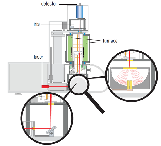
Laser Flash Measurement Principle
The sample is placed on the sample robot inside the furnace, and the furnace is maintained at a preset temperature. At this temperature, one surface of the sample is irradiated by a programmed energy pulse (laser or xenon flash), causing a uniform and transient temperature rise on the sample surface.
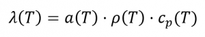
The temperature rise on the rear side of the sample is detected by a high-speed infrared detector. Thermal diffusivity α is calculated from the temperature–time curve, and in many cases the specific heat capacity cp can be obtained as well. When density ρ is known, thermal conductivity λ can be calculated as:
System operation is compliant with national and international standards including ASTM E1461, DIN 30905, and DIN EN 821, supporting highly reliable, standardized thermal conductivity testing.
Vertical Measurement Configuration
The system uses a vertical configuration: the infrared detector is located at the top, the sample is in the middle, and the heat source (laser) is positioned at the bottom. This setup offers both convenient operation and an optimized signal-to-noise ratio. Pulse energy is adjustable from 0.05 to 25 J per pulse, and pulse width can also be configured as needed, enabling optimized measurements for thin films and ultra-low thermal conductivity materials.
Models and Technical Specifications
Measurement Capabilities of LFA 1000 and LFA 2000
- Temperature range (LFA 1000): -125 / -100 to 500°C; RT to 1250°C; RT to 1600°C (depending on furnace configuration)
- Temperature range (LFA 2000): RT to 2000 / 2400 / 2800°C (depending on furnace configuration)
- Pulse source: Nd:YAG laser, up to approx. 25 J per pulse
- Temperature detection: Non-contact infrared detector (InSb or MCT)
- Thermal diffusivity range: 0.01–1000 mm²/s
- Thermal conductivity range: 0.1–2000 W/(m·K)
- Heating rate: 0.01–20 K/min
- Sample size (LFA 1000): Diameter 3, 6, 10, 12.7…25.4 mm; square 10×10 or 20×20 mm
- Sample size (LFA 2000): Diameter 6, 10, 12.7…25.4 mm
- Sample thickness: Up to approx. 6 mm
- Number of samples (LFA 1000): Autosampler supports 3, 6, or 18 samples
- Number of samples (LFA 2000): Autosampler supports 3 samples
- Sample holder materials: Metals, SiC, graphite, etc. (selectable based on material and temperature)
- Liquid sample holder: Optional
- Atmospheres: Inert, oxidizing, reducing, and vacuum modes
* Actual specifications may vary depending on system configuration and optional modules
Measurement and Evaluation Software Features
The system is PC-controlled and runs on the Microsoft® Windows® platform. The complete software architecture includes three main modules: temperature control, data acquisition, and data evaluation. It provides standard functions required for thermal analysis experiments and dedicated algorithms optimized for flash method testing.
Key Features of the LFA Evaluation Module
- Pulse length correction and pulse mapping.
- Heat loss correction.
- Two-layer and three-layer sample analysis.
- Model wizard to support appropriate evaluation model selection.
- Specific heat capacity (cp) determination and comparative method analysis.
- Determination of thermal contact resistance in multilayer systems.
Measurement Software Functions
- Intuitive programming of temperature profiles and atmosphere settings.
- Sample robot control for automated multi-sample measurements.
- Automatic display of corrected measurement curves after each pulse.
- Fully automated measurement programs for multi-sample and multi-step temperature conditions.
Software and Accessory Options
- Support for Chinese-language user interface.
- Raw measurement data export to Excel format for further analysis and documentation.
- Multiple sample holder designs and material options.
- Gas control boxes: manual, semi-automatic, and fully automatic (MFC), up to four gases.
- Rotary vane and turbomolecular pump options for vacuum and special atmosphere operation.
Typical Applications and Test Examples
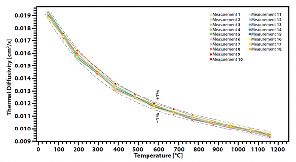
Repeatability Test of Thermal Diffusivity for Glass Ceramics
A glass-ceramic material (Pyroceram) was used as a high-temperature reference material, and multi-point thermal diffusivity measurements were performed using the LFA 1000. Multiple specimens cut from different positions of the same plate were tested. Eight independent measurements were performed within the temperature range up to 1250°C, and the results showed that the deviation in thermal diffusivity remained within ±1%, demonstrating excellent repeatability and stability of the system.
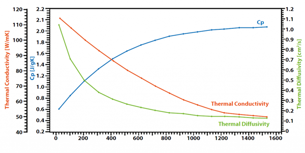
Thermal Conductivity, Thermal Diffusivity, and Specific Heat of Glass Ceramics
Using a standard glass-ceramic sample (e.g., BCR 724) as an example, bulk material is machined into thin discs with a thickness of about 1 mm and a diameter of 25 mm, then coated with graphite. Thermal diffusivity is measured directly by the flash method, specific heat capacity cp is obtained by the comparative method, and thermal conductivity is calculated using density. Results show that specific heat increases with temperature, while thermal diffusivity and thermal conductivity slightly decrease with temperature.
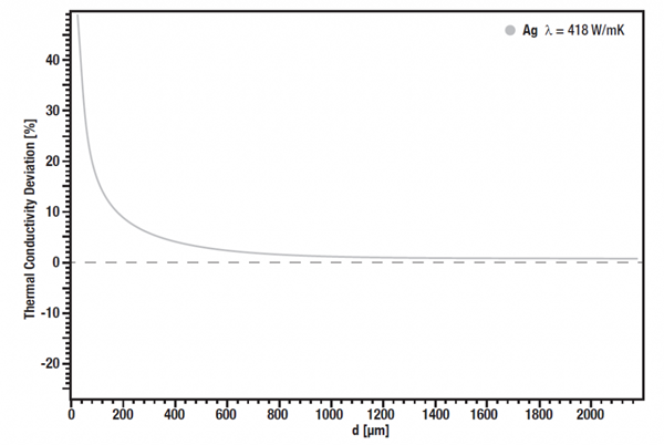
Effect of Sample Thickness on Thermal Conductivity Accuracy
A standard silver sample was used to study the influence of sample thickness on thermal conductivity accuracy. At room temperature, standard silver specimens with different thicknesses were measured. Thermal conductivity was calculated from α, ρ, and cp, and compared with literature values. Results indicate that as the sample thickness decreases, the deviation of thermal conductivity continues to improve and reaches an optimal region around 200 µm. For even thinner samples, it is necessary to consider that thin films may behave differently from bulk materials. In this case, thin-film-specific thermal conductivity measurement techniques are recommended.
Technical Video
Mobile: +886-919-138-108
Email: Allen.kuo@fstintl.com.tw